POVENDHAN A P

OPTIMIZATION RESULTS
Force flow
HOW TO INTRODUCE SIMULATION DESIGN OF AUTOMOTIVE GEARBOX?
To explore different simulation tools used for topology optimization and to improve the methodology and process with higher design interpretability for static topology optimization.
CONTRIBUTION
Independent Research
Topology optimization
Methodology development
SKILLS
CAD modelling
FE modelling
FE Analysis
Structural Optimization
OUTCOME
Way of Work proposal
Design volume selection
Response Function Selection
Parameters Selection
THE INTENT
The intent of the study is to improve the optimization ability to form manufacturable designs through identifying the software approaches, initial design modelling, mathematical response functions, constraints and choosing appropriate parameters. The intention is also to develop a methodology of simulation driven design that can be integrated into the design process to make informed analytical decisions.

OPTIMIZATION
Simulation driven design | Design volume | Gear box housing
Topology optimization | Meshing software | Finite Element
THE OPPORTUNITY
UNDERSTANDING TECHNOLOGICAL COMPLEXITY AND CHALLENGES ?
CURRENT OPTIMIZATION RESULT

The T. O result from the current optimization methodology followed at GKN. As can be clearly seen, distinct rib structures are not visible. Hence, the knowledge transferred, and the usability of the T. O result is lesser during the design realization.
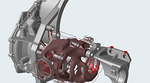
COMPONENT

The component considered are housing structure, cover, gearbox and the bracket. The housing structure and the cover, the bracket and the gearbox are considered for a more realistic representation of the boundary condition in order to avoid infinitely stiff boundary conditions at the mounting points of the housing and cover.
GRADIENT BASED DUAL OPTIMIZATION ALGORITHM METHOD

The concept of gradient based optimality method is explained in a simplified way by using an objective function of 2 independent variables x1 and x2. This method works by calculating the steepest ascent or descent from a point and taking steps for optimization in this direction.
PROBLEM IDENTIFICATION

The complex nature of the housing geometry. Optimization tends to give clear results for simple structures and the results become messy when the complexity increase.
DESIGN VOLUME SPLITING

The Domain Sub-domain approach cannot be used directly but the principle of this approach is carried forward in simplifying the design volume. Translating this method is done by choosing the appropriate geometry of design volume to get the best T.O results.
MOUNTING POINTS
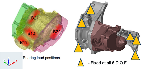
The bearing forces obtained from the system calculation department at GKN are applied to the PTU housing through 1 dimensional rigid body elements (RBE). Similar to the bolts, the mounting points at the gearbox and also at the brackets are modeled using RBE2 elements.
HOW DOES DESIGN VOLUME AFFECT OPTIMIZATION ?
APPROACH 1

To build the optimization model with this approach, a non-design space as shown in figure is defined as the four bearing seats and the bolt holes.
APPROACH 2

Design volume 2 when modeled using inspire proved to be inefficient due to the geometric complexity of the non-design space. HyperMesh is the best suited for this design complexity.
Optimization result Approach 1 Optimization result Approach 2


HOW DOES THE APPROACH OF SOFTWARE AFFECT THE RESULTS?

INSPIRE
Automeshing

SIMLAB
Semi-auto meshing

HYPERMESH & OPTISTRUCT
Manual meshing
TOPOLOGY OPTIMIZATION
INSPIRE
Optimization configuration
Analysis Type: Static
Objective: Max stiffness
Constrain: Stress and 30% vol
Loads: Static Drive/Coast
Non-design space: Design volume 1

TOPOLOGY OPTIMIZATION
SIMLAB
Optimization configuration
Analysis Type: Static
Objective: Min compliance
Constrain: Stress and 30% vol
Loads: Static Drive and Coast
Non-design space: Design volume 1

TOPOLOGY OPTIMIZATION
OPTISTRUCT
Optimization configuration
Analysis Type: Static
Objective: Min Compliance
Constrain: Stress and 30% Mass
Loads: Static Drive and Coast
Non-design space: Design volume 1
UTILIZING THE ADVANTAGES OF DESIGN VOLUME AND SOFTWARE APPROACHES IN OPTIMIZATION...

LOOP 1
Initially, primary rib structures are formed with less model complexity. This loop uses the design volume approach 1 using inspire and static loads.

LOOP 2
The reinforced rib structures are formed with higher model complexity in loop 2, leading to results with clear visualization. This loop utilizes the design volume 2 in the second approach with static and dynamic loads.
TOPOLOGY OPTIMIZATION RESULTS

COMPARISON OF TOPOLOGY OPTIMIZATION RESULTS
The main objective for the thesis is to increase the design interpretability of the results of the T. O. Figure 73 shows the T. O result from the current optimization methodology followed at GKN. As can be clearly seen, distinct rib structures are not visible. Hence, the knowledge transferred, and the usability of the T. O result is lesser during the design realization.
VALIDATION

STRESS AND RIBS COMPARISION
These stress patterns are compared to the topology results and it is observed that material deposition was predicted by the topology optimization at the location of these stress patterns.

ANALYSIS AND RIBS COMPARISION
The rib structures are not generated in a single stage optimization the possibility for eliminating the globally optimum design has increased because of the manual interference in the optimization.

PROPOSED TOPOLOGY METHODOLOGY
This methodology is developed as a combination of two of the optimization methodologies mentioned in the theory section i.e domain --> sub-domain and sequential optimization methodology.